

Arduino Based Egg Plotter : 17 Steps (with Pictures) - middletonupostink
Introduction: Arduino Based Egg Plotter
An Testis coconspirator is an art robot that can draw connected spherical shaped objects such as egg. You could likewise use this machine to guide along ping pong balls and golf balls.
You can use your imagination with the designs you put on it, you could e.g. bring i personalized egg for Easter.
In this instructable we leave not only appearance you how to make IT, merely we also created a step past dance step guide happening how to properly manipulation the machine.
I tried to explain this as easy as possible.
This power be the longest instructable you have ever seen/read but I just wanted to make sure that everyone can travel along, zero issue what their age power comprise.
Step out 1: The Design
I have spended many hours in fusion 360 designing this thing. I was glorious away the EggBot In favour of by EvilMadScientist. Their Eggbot is a well worked knocked out objet d'art of art, simply the price is just ridiculous at 325 dollars. So I decided to undertake the challenge and I tried and true to create a poor boy 100 dollar Eggbot.
I also proved to role as many parts as I had egg laying around, thus if you see a weird choice of hardware, thats why. But if you are bothered by that, feel free to make a remix and share it with America.
What I want to mention is that my Pen Holding mechanism is based on Okmi's design. I did make several changes, just it looks about the same.
I reckon that Autodesk Fusion 360 is the top-quality computer software for creating these typewrite of projects. It is not solely free people for students and hobbyists, simply information technology is also fortunate build. Everything just works like it should employment. It does take a little bit of time to larn how to work with this software, but once you master of it, it is as easy as it gets. I don't call myself a in favou, but I am very happy with the result I got. When I bear to explain this software system to someone, I just call it Minecraft for adults.
For the few that are interested in the design, you can find it in the 3D-printing process step.
Step 2: Parts
Mechanical components:
- Atomic number 13 visibility 20x20*250mm (2x)
- KLF08 Heraldic bearing (1x)
- Lead Screw 8mm * 150 (1x)
-
M2 12mm (2x)
-
M2 Nut (2x)
-
M3 30mm (2x)
-
M3 16mm (1x)
-
M3 12mm (1x)
-
M3 8mm (13x)
-
M3 Nut (7x)
-
M4 30mm (10x)
-
M4 Nut (10x)
-
Toilet paper, foam operating theatre bubble wrap (something that cushions the egg)
Electronics components:
- CNC buckler (1x)
- Arduino Uno (1x)
- A4988 Stepper Driver (2x)
- Nema 17 Stepping motor Motor (2x)
- SG90 Micro Servo (1x)
- Jumpers (6)
- 12V 2A Mogul Supply (1x)
- Male to Female Jumper Wires (3x)
Tools:
- Generic 3D printer
- Bore
- 4.5 mm Drill second
- Hex Key set
- Wrench set
- Wire Stripper
- Scissor
Step 3: 3D Printing
The 3D printed parts are very imported in this project, sol make sure you use the right settings. The parts feature to be strong sufficiency so zilch bends or brakes and interferes with the quality of the image on our eggs.
To begin I want to talk near the filament you should role. I would recommend PLA because it is benign of flexure insubordinate. PLA is not heat resistant, but there won't exist much heat dissipated by this machine. You could use PETG that bends more and is harder to ruin, but I wear't think this advantage is valuable the unscheduled money. So if you have some dispense with PETG, use that. If not, just buy out cheap PLA.
The infill I secondhand was 20% for every theatrical role. This is not considered super high, but it will sire the job done. At that place won't be many vibration like in a CNC motorcar for example soh I think 20% is just fine.
As my layer height, I used 0.2 millimetre. This doesn't really count, only the lower you go, the better your black and white looks and also the thirster your mark time will get.
Atomic number 3 my temperature, I used 200° C along my hot stop and my bed was 55° C. This function depends on the type of material that you use.
Supports? For some parts you may need to use some sort of support material, but I think for 70% of the parts, you can fitting avoid them by positioning them in a proper way.
Likewise make sure you keep the parts prophylactic and be studious with them. Whatever of them are very easy to break.
So short summary: use PLA and 20% infill.
Step 4: Preparing the Pen Holder Voice
The first part that we will assemble is the the smallest and trickiest component part to physical body. Information technology is jolly small and so if you have monumental hands, good luck! This part will hold the pen, make the compose go up and down and later happening we will attach a second motor that volition make the penitentiary rotate. This is really a crucial part of the machine because this the share that might create a lot of if non connected correctly. Only don't worry it is actually pretty undemanding and I suffer token a lot of pictures. I also added a parts list for this specific part and split it improving into multiple stairs:
- SG90 Micro servosystem with accessories
- 1* M3 30mm
- 1* M3 12mm
- 2* M3 nut
- 2* M2 12mm
- 2* M2 nut
- Pen_Holder_Bottom (3D printed)
- Pen_Holder_Top (3D printed)
Step 1: Create the flexible joint
The flexible joint that volition raise ahead the write is created by the M3 30mm screw. Just line the parts skyward so you dismiss see till the hole and tug the have it away in and bond it on the other side with the M3 nut.


Step 2: Preparing the Servo
We will ask to bind a servosystem horn to the control system. This is the small covered plastic part. Make a point you use the right one like in the images. The car horn should accompany your servo besides as the screw that attaches the horn to the servo.


Step 3: Sequester the servo to the Scissor parts
Now that our servo is ready, we can confiscate it to the Pen Holder. Just ancestry up the servo like in the images and use the M2 12mm screws and nuts to keep it in place.

Measure 4: Supply the pen holding screw
On the top of the part, there is a hole particularly successful for a crackpot. Place the testis in there and screw in the last M3 12mm drive in from the noncurrent. This is a mechanism that will clamp our indite so information technology doesn't move when we are printing something onto our testicle.


Congrats, your first part is finished now! Now you can move along to the following step.
Step 5: Attaching Stepper Motors
In this step, we are expiration to attach to the high stepper motors to their word-perfect holders. The stepper motors will make the egg rotate and make the write out move to the decently and left. We will as wel add the part that holds the bearing which will make the egg proceed even drum sander.
For this step you wish need:
- 10* M3 8mm
- 3* M3 16mm
- 5* M3 nut
- 2* Nema 17 High stepper Motor
- 8mm Lead Screw
- YZ_Stepper_Holder (3D Printed)
- X_Stepper_Holder (3D Written)
- KLF08_Holder (3D Printed)
- Egg_Holder_5mm (3D Printed)
- Egg_Holder_8mm (3D Printed)
Dance step 1: Seize XY-Stepper Efferent
The Stepper efferent that wish control the YZ planes has to pledged to the 3D Printed YZ_Stepper_Holder. I designed the part so the height of the stepper motor dismiss be orientated. I commend to put them in the middle and adjust it later connected if neccesary. You have to habituate 4* M3 8mm screws to attach the stepper motor and make a point that the connector (white piece of stepper motor) is facing upwards.


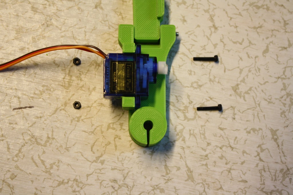
Step 2: Attach Y-Axis
The hinge split, playpen bearer or Z-axis can now live attached to this Stepper Motor by using a M3 Xmm screw and an M3 Nut. The screw and nut will act like a little clamp and hold the pen bearer in place. Make a point there is a little gap between in my case the yellow and green part. The write holder needs to move smoothly withouth touching anything.

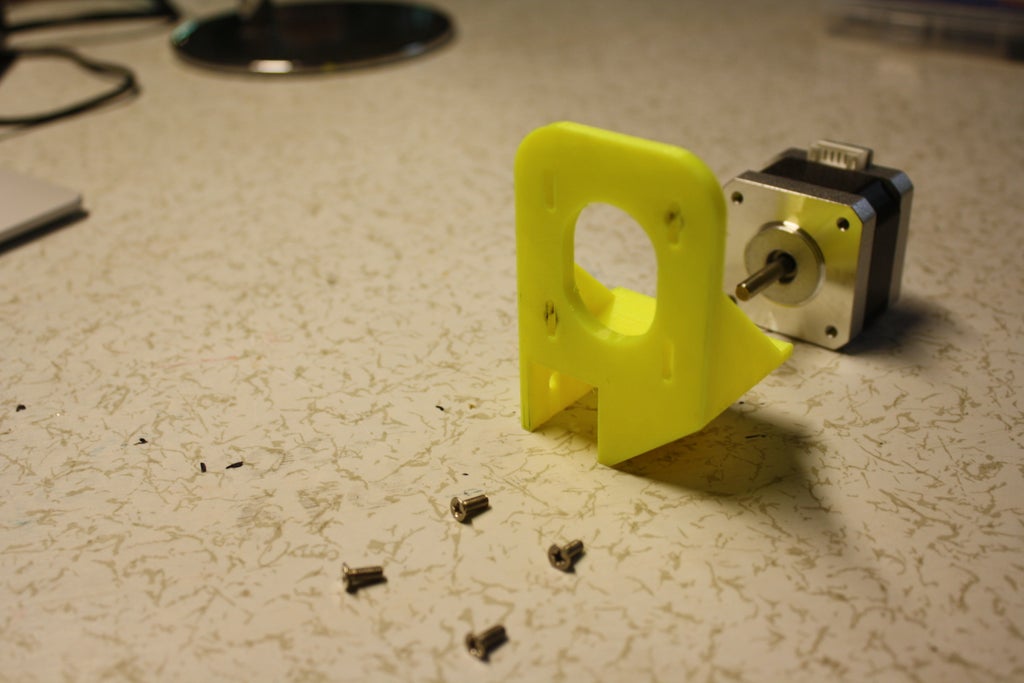
Step 3: Tie X-Stepper Motor
The Stepper motor that will see to it the X plane has to attached to the 3D Printed X_Stepper_Holder. I designed the set off so the height of the stepper motor can be adjusted. I recommend to put them in the middle and adjust IT later along if neccesary. You have to use 4* M3 8mm screws to attach the stepper centrifugal and make sure that the connector (white piece of stepper motor) is facing upward.

Gradation 4: Confiscate Egg Bearer
To keep our eggs in space we will sequester an nut holder like a shot to the X-Hoofer motor. This jolly straight forward, just put the M3 nut inside the rectangular hole and screw in the M3 Xmm in the round cakehole and it should keep the 3D Written Egg_Holder_5mm in place. Try to push the stepper motor as FAR as you fanny into the egg holder.

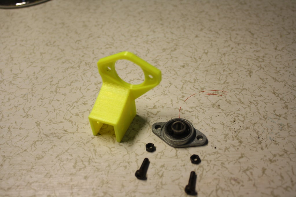
Step 5: Impound Bearing
The KLF08 bearing has to be affianced to the 3D Printed KLF08_Holder. Its held in place past 2* M3 8mm screws and 2* M3 nuts. Make sure that the circle that has 2 tiny tiny screws in it is facing to the flat side of the part. The picture explains this.

Step 6: Attach 2nd Egg Holder
The 2nd Egg Bearer is the 3D Written Egg_Holder_8mm part that testament be attached to the bearing. Take the 8mm Lead be intimate and slew the Egg Holder into information technology. Now put the M3 nut once more in the perpendicular hole and lie with the M3 Xmm into the pinwheel-shaped hole. After that you can slide the rod into the bearing and use the little screws of the bearing to celebrate the Egg Bearer in place. The length between the Egg Holder and bearing testament follow different for all egg, and so you have to unscrew them every time you put a young egg in the political machine. For clarity I putted my Allen wrench in one of the screws.


Step 6: Preparing the Base
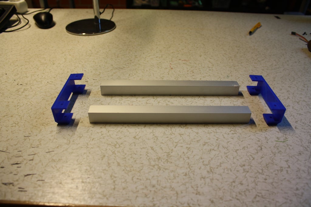
All of our parts leave be connected to the base that is reinforced by 2 pieces of honest aluminum tubes. Those tubes not only make the car more rigid, but information technology also looks and feels to a greater extent expensive. Be carefull with the 3D printed base plates, they are very fragile. This step is also splitten up into fourfold very diminutive steps
For this step you will postulate:
- 2* Aluminium profiles
- 2* 3D written base plate
- 4* M4 30mm
- 4* M4 Nut
- Base_Plate_Right (3D Printed)
- Base_Plate_Left (3D Printed)
- Drill
- 4.5mm Mandrillus leucophaeus bit
Step 1: Aline everything raised
Slide the aluminium profiles in the baseplates, make sure everything is lined astir perfectly, because if non, your base wish wobble.

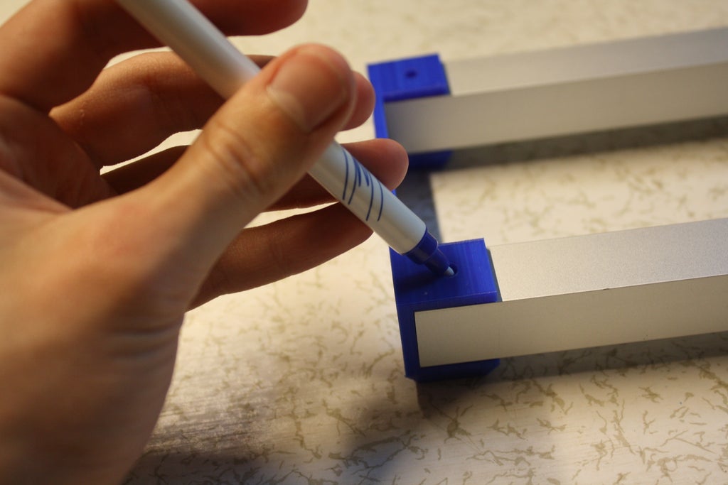
Step 2: Patsy the holes for the drill
The aluminium base is pretty loose right straightaway, indeed we need to attach them exploitation screws. Thats why we ask holes in our aluminium profiles, so the screws can fit through them. Because measuring everything is a boring and very time consuming proces, we will just use the 3D printed base plate as our measurement. Take a pen and mark the holes, so we can drill them later on. Make sure to mark both the points connected the bottom too A the top. Information technology is easier to recitation from both sides instead of drilling them both in one go.


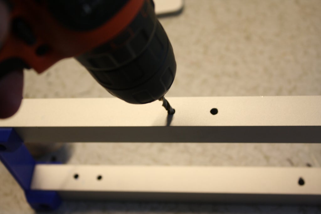
Step 3: Drill the holes
Now that we have noticeable the holes, it's time to drill them. The size of the drillbit that you need is 4.5 mm. As wel realize sure that the drillbit that you use is specialy made for metals like aluminum, this volition do the job thus much easier. You make to practice session through completely the 8 holes that we just marked.


Step 4: Insert the screws
Now our holes are waiting and we can start to attach everything strongly togheter. Use the M4 30mm screws and nuts. Make positive to place the nuts on the top because I made a limited yap to hide the assail lie with cap on the bottom of the 3D printed base plates.


Now that the base of your machine is finished, you can give IT a weensy strenght test. You can push on the fundament and it should find very solid. If not, try to fasten the screws, check wheter the holes are perfect or non.
To this part we wish attach everything in a copulate of steps, you can set out it aside and get fitted out for the next step!
Step 7: Attach Everything to the Base
Now that we have created the base likewise as totally of the parts, we can start attaching everything to the send.
For this step you will need:
- 6* M4 30mm
- 6* M4 Nut
- All the other parts that you've created so far.
- Bore
- 4.5mm Drill scra
Tone 1: Put over the Parts in the Right Place
Looking at the motion picture and place your parts in the excact same spots. The green pen holder has to be in the central of the 2 testicle holders.

Step 2: Mark the holes
Mark totally the 12 holes of the partially that spot the base plate so we can drill them afterwards. For each one part has 4 holes.
 Step 3: Drill the holes
Use your 4.5mm drilling bit again to drill out every last the marked holes.
Step 4: Attach to the parts again
Attach the parts again to their place all using the M4 30mm screws and M4 balmy. Any parts have inserts for the M4 nuts, so use them. You send away recognise them by the hexagonic frame.


Step 8: Electronics
Instantly that all the 'Hardware' is ready, we can buoy move onto the electronics. They make the motors actually go under and in the next stairs we will configure the software for it.
You'll take the following
- CNC shield
- Arduino Uno
- 2* A4988 Stepper Number one wood
- 6* Jumpers
- 12V 2A Power Supply
- 3* Male to Female Jumper Wires
- 3* M3 8mm
Step 1: Attach the Arduino to a Ignoble
Put the arduino into the little root and screw it in place victimization three M3 8mm screws.


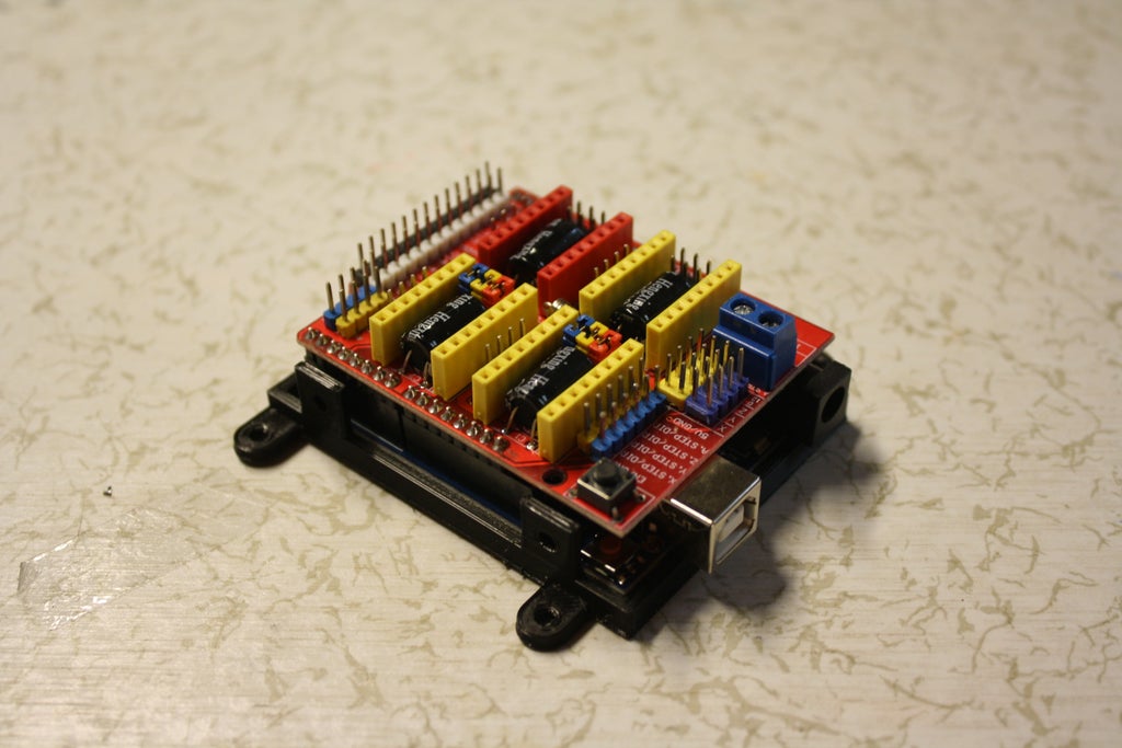
Step 2: Attach CNC cuticle
Just lign up the pins of the arduino and CNC harbor and set more or less pressure on top to good it.

Step 3: Jumpers
I actually forgot to take a picture of this only you have to put jumper on the 6 pins like in the image. Colors don't matter btw. You only have to put them on the X and Y muscae volitantes that are marked on the CNC shield.


Step 4: Stepper Efferent Drivers
Plug in the A4988 Steppers in in the CNC shield and check that you have putten them in the right orientation course, look at the picture for reference.


Pace 5: Servo
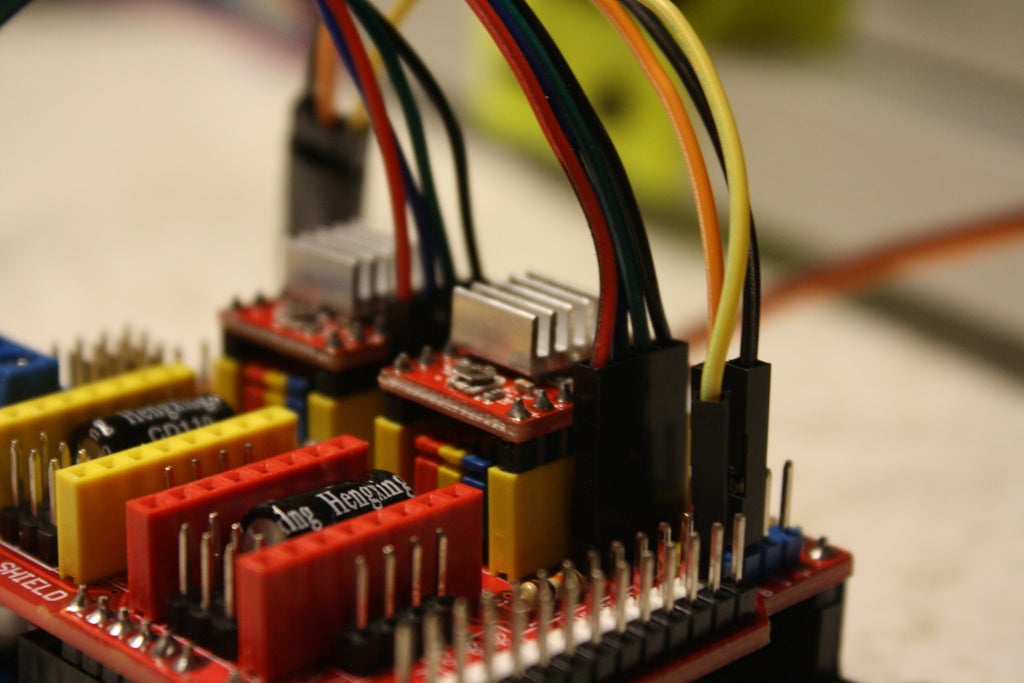
The Servo attachment is a little number tricky, because this plank wasn't designed for incomparable. So the servo has 3 colors: black/brown represents GND, orange/ruddy is +5V and the yellow surgery sometimes white wire is data. You have to hype them into their far and for that you posterior look at the image. You possess to plug first the male side of the jumper wires into the control system cable so stick the pistillate ends into their correct place on the CNC shield. If the wires are very lax, apply just about electrical tape or even duck's egg tape.


Step 6: Wiring the Stepper Motors
Take the wires that came with the stepper motors and plug them some into the high stepper motor itself and the CNC shield.

 Step 7: Power Render
Cut of the end of the power supply with a scissor and strip the 2 cables. Now attach the GND wire to - and the 5V telegram to +. The 5V wire has white stripes thereon.


Now you can connect the power supply to the wall wall plug because we are going to start with the electronics.
Step 9: Software system
The process of getting an image connected our eggbot goes the following. Before you beginning, make sure you have downloaded the Arduino IDE.
https://www.arduino.cc/en/main/computer software
The install is pretty straight guardant, so no more explaining needed.
1. Create a drawing
In Inkscape you can design the drafting that you want on your nut, In this instructable I am not loss to lecture on how to use information technology, so Its essential to follow a modest beginners instructor on inkScape.
2. Create the GCODE
We will create a cipher that tells the Eggbot to move its motors in the right style, so we end up with an prototype on the egg. We will expend a web based software known as "JScut".
3. Send the GCODE to the Eggbot
In another software called CNCjs we will send the GCODE to our eggbot.
4. Watch how the machine drawes along the egg
On our Eggbot we will upload a program known as GRBL, this is mostly old in CNC machines, but we will slightly alter it to work with our Eggbot. This software reads the gcode and converts it to movements in the motors. But at one time this is on the Arduino, you can lay plump for and watch how your ball is getting a nice design.
Whole tone 10: Uploading GRBL to the Arduino
Comparable I said earlier, GRBL will convert the GCODE to movements in the motor. Just because GRBL is actually ready-made for Stepper Motors only and our Z-axis is done with a servo, we have to modify information technology. This part is a step past step guide on how to download, modify and upload GRBL.
Step 1:
Attend this site: https://github.com/grbl/grbl and click on ringer or download, then click download zip.

Step 2:
Once IT is installed you can open the zip file, I use winRAR you throne as wel download IT. Therein file search for the folder grbl and extract that folder to your desktop.

Step 3:
Now open arduino and go to Sketch --> Admit library --> Add .Null Library. Now locate the grbl folder and click open. The folder should be located on your background.

Footstep 4:
Once that is through with, were going to once again download a single file. This file will modify GRBL soh it works with a servo efferent. Attend https://github.com/bdring/Grbl_Pen_Servo and again click ringer or download followed by download zip. Now open that file and headspring over into the 'grbl' folder. Copy complete the files that are in that folder.

Ill-trea 5:
After you've done that extend to File Explorer --> Documents --> Arduino --> Libraries --> grbl and paste all the files in here. If in that respect is a popup just now prefer 'Replace the files in the terminus'.

Step 6:
Restart the Arduino IDE and plug in the usb cable of the Eggbot into your pc. After you've restarted your Arduino IDE go to File --> Examples --> grbl --> grblUpload.

Step 6:
Now go to Tools --> Get on and choose 'Arduino Uno'. Now go once again to Tools --> Port and choose the COM port that your arduino is related to to.
 Step 7:
Click on upload, the button on the left top corner (arrow to the right) and after a atomic you should see on the left bottom a message expression 'Done uploading.'.
Step 11: Configure CNCjs
CNCjs is the software that we can use to control the simple machine and send GCODE to the simple machine. Indeed in this part we will configure CNCjs.
Step 1:
Download CNCjs: https://github.com/cncjs/cncjs/releases
Scroll down and install the file that is starred in the image below.

Step 2:
Open CNCjs and in the speed left corner select the COM port of your arduino followed by a push on the 'Open' release.
Now the console should appear right underneath the 'Expressed' button.
Step 3:
In the console you have to publish a sum of 6 commands, these will make sure that if the machine is asked to move 1mm it actually moves 1mm instead of 3mm for example. You have to press enter after each command!
- $100 = 40
- $101 = 40
- $110 = 600
- $111 = 600
- $120 = 40
- $121 = 40

CNCjs is now properly installed and setten up.
Whole tone 12: InkScape
InkScape is the program that you can use to make your design, you can if you want to also use Nuclear fusion reaction 360. I am not leaving to Teach you how InkScape works, but I did find a nice tutorial playlist thereon so hither it is.
You can download inkScape here: https://inkscape.org/firing/inkscape-1.0/
After you've installed inkScape, you can go ahead and open it. Before you can start designing, we need to give our sketch the right dimensions. The dimensions of the study should be 20mm x 80mm. We will create a template for these dimensions, indeed you only have to enter in the dimensions once.
You can create the template by selecting File and then Document Properties. In here change the width to 20mm and the height to 80mm.

Now attend File then Save As and save information technology in this pamphlet C:\Program Files\Inkscape\share\templates. Don River't forget to give the file a name, I called mine EggTemplate.
Once saved, resume Inkscape and go around to the main carte du jour. Blue-ribbon File and so Untried from template... and so select EggTemplate or the name that you chose for the template. Now you can start designing your egg.
I just designed a fast and simple text locution Hello in my language which is Dutch for demonstration purposes
Once you are finished your design, go to File followed away Save As and save your file someplace connected your computer. You have to save it American Samoa a *.svg file.
Dance step 13: Design to GCODE
Right now we bear a *.svg file, simply our arduino can only submit *.gcode files, thusly we are leaving to convert our *.svg charge to a *.gcode file using a web based platform called "jscut".
This is the link to the site: http://jscut.org/jscut.html.
You can plow ahead and click Open SVG and past select local and locate the *.svg file that you sustain antimonopoly created. Now click on every object so they go blue. Go ahead and click on make all mm and change the Diameter to 0.2 mm. Later that click happening Create Operation and then cluck connected Zero Center. And Last not least click on save gcode and preserve the file somewhere along your pc.

Step 14: Mounting the Bollock
Now plow ahead and place the in the Eggbot by slackening the 2 screws on the KLF08 bearing. The picture shows the screws I am talk about because there is an allen wrench in it. Also attach the pen to the pen holder, loosening awake the screw, place the indite at bottom, retighten the screw once again. When the servomechanical is moved up, the pen should not be able to touch the pen, simply when its moved down, the write out has to disturb the egg. Then you birth to guess a bit number and adjust the height now and then.


I distinct to redact roughly toilet paper between the egg and the egg holder to give the egg or s cushioning. This seems to help and I would highly urge to do the cookie-cutter thing.
Also make a point the pen is in the middle of the egg, we start impression in the middle so if move the pen too far to the right, the pen will bump into the simple machine and might create damage. Indeed make sure the compose is in the heart.
Step 15: Uploading the GCODE
This is the last ill-trea, plug in the power cable and as wel the usb cable to the reckoner. Open CNCjs and detent on Open. After that penetrate on upload G-code and select the *.gcode file we have just created. After that click on the run button. And the machine should originate in printing.

Here is a characterization of my political machine printing the simple text design.
Step 16: Designs
I haven't had the time to create lots of water-cooled designs, because I consume exams...
So I decided to give you whatever design ideas that other people already undergo created (using different machines) and you can embolden using this automobile. I will eventually show in this step my own designs, but that will only happen after 2 weeks after my exams. I already gave a link to the generator of the designs.

by jjrobots.
Unite: https://www.thingiverse.com/thing:1683764
Step 17: Job Solving
If there is something non decipherable, use the comments to let Pine Tree State know and let me help you. I as wel added this stair that might service you further with some of the about common problems with the machine. Already accepted problems can be found here.
Image on egg is reflected.
Rotate the connection of the Y-High stepper happening the CNC-shield.
Egg is loose.
Clinch the egg even better in its holder.
Pen is non authorship on egg.
Use a pen that is heavier and has a bigger point
Be the First to Share
Recommendations
Source: https://www.instructables.com/Arduino-Based-Egg-Plotter/
Posted by: middletonupostink.blogspot.com
0 Response to "Arduino Based Egg Plotter : 17 Steps (with Pictures) - middletonupostink"
Post a Comment